Motor Slot Wedge Materials, Applications & CNC Machining Process
motor slot wedge materials, applications and CNC machining requirements. Discover G10, G11, FR4 and epoxy glass laminated slot wedges with precision CNC machining for electric m...
Application and CNC Machining Requirements of Slot Wedges in Motor Manufacturing
In motor manufacturing, the slot wedge is figuratively referred to as the “anchor” of the coil winding. It is locked into the slot opening of the stator or rotor core to securely lock the coils in place, preventing them from popping out under the intense centrifugal force of high-speed rotation or electromagnetic vibration.
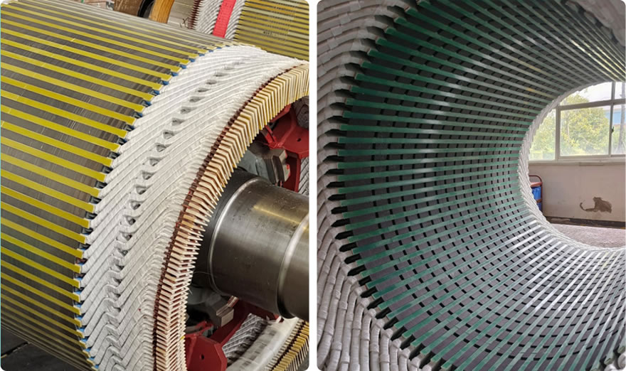
Different types of motors (low-voltage, high-voltage, traction motors, New Energy Vehicle [NEV] motors, and large generators) require different slot wedge materials. The mainstream materials currently used in the market include the following:
Mainstream Slot Wedge Materials
| Material Type | Common Grades / Models | Temperature Class | Application Status |
| Epoxy Glass Cloth Laminated Sheets | G10, G11, 3240, EPGC201, EPGC203 | Class F (155°C), Class H (180°C) | The most widely used material, holding the largest market share. |
| Phenolic Glass Cloth Laminated Sheets | 3230, 3231 | Class B (130°C) | Used in legacy motors and standard industrial motors. |
| Phenolic Paperboards | 3020, 3021, 3023 | Class E (120°C) | Used in small low-voltage motors; usage is gradually declining. |
| Polyimide (PI) Laminated Sheets | PIGC301, PI | Class C (220~240°C) | Used in high-end traction motors and aerospace applications. |
| PAI Laminated Sheets | Polyamide-imide | Class H / Class C | Used in high-speed motors and military-grade motors. |
| Benzoxazine Glass Cloth Sheets | Benzoxazine Laminate | Class H (180°C and above) | An emerging alternative material featuring excellent heat resistance at a lower cost. |
Common Cross-Sectional Profiles for CNC Machining
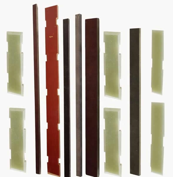
The design of the motor core slot determines the cross-section of the slot wedge. CNC milling machines can produce various profiles using custom form cutters or 3-axis/4-axis simultaneous machining:
Rectangular / Flat Strip: The most basic shape and the easiest to machine. It can be directly slit and cut into individual strips using standard carbide external cylindrical milling cutters.
Trapezoidal / Beveled: The most common profile for industrial asynchronous motor slot wedges. Both sides are machined with a specific bevel angle (such as 15°, 30°, or 45°) to perfectly fit into the sloped shoulders of the stator slot openings.
Stepped / Grooved (T-Shape): Used in high-voltage motors or double-layer winding motors. It features raised steps on both sides to maintain specific electrical clearances while locking down the coils.
Radiused / Chamfered: To prevent the slot wedge from tearing the slot liner insulation paper or scratching the coil magnet wire insulation enamel during insertion into the stator slot, chamfers or radii are typically machined onto the front head or the long edges.
CNC Machining Process Requirements for Epoxy Slot Wedges
1. Grain-Aligned Nesting (Ensuring Flexural Strength)
Process Requirement: When nesting parts in the CAM software, the length of the slot wedge must be aligned with the longitudinal direction (warp direction) of the epoxy sheet, where tensile and flexural strengths are highest.
Core Purpose: To ensure that the slot wedge possesses sufficient mechanical rigidity to prevent snapping when driven into the stator slot with a pneumatic driver or when subjected to the massive centrifugal forces of a rotor.
2. Vacuum Chuck Fixturing (Preventing Micro-Warping)
Process Requirement: Eliminate traditional mechanical clamps or vises. The entire epoxy sheet must be laid flat on a vacuum suction platform, with a medium-density fiberboard (MDF) placed underneath to serve as a sacrificial spoiler board.
Core Purpose: Epoxy sheets are generally thin (2 to 4 mm), and vacuum fixturing ensures the sheet remains perfectly level. If the sheet warps or vibrates slightly during machining, it will cause inconsistent wedge thickness and leave the edges highly prone to chipping.
3. Precision Tool Selection (Down-Cut Cutters and Router Corn End Mills)
Roughing & Slitting: Use CVD diamond-coated corn end mills (also known as router or pineapple cutters). Their dense, cross-cut cutting edges shatter the hard fiberglass cleanly to reduce cutting forces.
Finishing Bevels / Steps: Left-hand helix, right-hand cut end mills (Down-cut cutters) or custom-angled tapered form cutters must be used.
Core Principle: As a down-cut cutter rotates, its cutting force pushes downward against the worktable, firmly compressing the top layer of the laminate. This completely eliminates industry headaches such as surface fraying, delamination, and edge chipping.
4. “High Speed, Fast Feed” Parameters (Preventing Resin Carbonization)
Process Requirement: Never dwell or use slow, grinding feeds. Recommended parameters: Spindle speed 18,000 to 22,000 RPM, feed rate 3,000 to 4,500 mm/min, and a single depth of cut (Ap) limited to within 0.5 times the tool diameter.
Core Purpose: Epoxy resin has extremely poor thermal conductivity. High spindle speeds combined with fast feeds allow the tool edges to slice through the material rapidly, evacuating the frictional heat along with the chips. If the feed rate is too slow, accumulated heat will cause the epoxy sheet to yellow and carbonize. Because carbonized sections become electrically conductive, this degrades the insulation class and forces the part to be scrapped.
5. Absolute Dry Cutting + High-Power Dust Extraction (Protecting Insulation and Machinery)
Process Requirement: The use of any water-based cutting fluids or oil-based coolants is strictly prohibited! High-power industrial dust extractors must be used, with the suction nozzle closely tracking the tool head for a fully dry machining process (supplemental cold air guns can be used for cooling).
Core Purpose: Once moisture contacts the freshly cut edges, it wicks into the micro-gaps of the glass fibers, severely compromising the insulation resistance of the slot wedge. Furthermore, fiberglass dust is highly abrasive and conductive; it must be evacuated at the moment of generation to prevent severe wear on the CNC linear guides and ball screws, or electrical short circuits inside the control cabinets.
6. End-Entry Lead Chamfering (Protecting the Coils)
Process Requirement: Before parting off and dropping the finished slot wedges, a radius (R) or a 45° lead-in chamfer must be milled onto both the front and rear ends of the wedge.
Core Purpose: Stator cores are very long, and slot wedges are driven in segment by segment. Sharp, unchamfered corners or burrs on the ends will easily tear the slot liner paper or scratch the enamel insulation of the copper windings during the driving process, resulting in a catastrophic ground fault.
Leave us a message to get quotation and sample!
If you are interested in our products,, please send us a message and we will contact you as soon as we receive it. Email: info@ztaero.com whatsApp: +8616650273778
Releated News
- 09-09 2026Phenolic Laminated Sheets | Grades, Applications & CNC Machining
- 09-08 2026Epoxy fiberglass Sheet Weight Calculation Formula
- 09-07 2026FR4 Epoxy Sheet for CNC Machining: Thickness Selection & Purchasing Guide
- 09-03 2026Black Bakelite Sheet: Introduction & Sourcing Selection Guide
- 09-02 2026G11 Epoxy Glass Laminate FAQ
- 08-31 2026Fiberglass Filament Wound Tubes for OLTC Transformer Insulation